Pages

Powered By Blogger

Saturday 12 November 2011

Power Plant Boiler


The boiler generates high pressure steam by transferring the heat of Combustion in various heat transfer sections. 
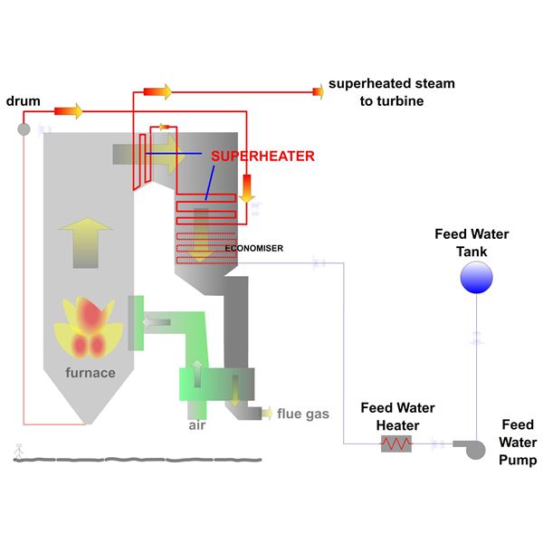
This part of the article series briefly describes the flow and arrangement of the heat transfer sections in a boiler. In line diagrams help make the concept clear.

 Basics

Volume of one unit mass of steam is thousand times that of water, When water is converted to steam in a closed vessel the pressure will increase. Boiler uses this principle to produce high pressure steam.
Conversion of Water to Steam evolves in three stages.
  • Heating the water from cold condition to boiling point or saturation temperature – sensible heat addition.
  • Water boils at saturation temperature to produce steam - Latent heat.addition.
  • Heating steam from saturation temperature to higher temperature called Superheating to increase the power plant output and efficiency.

Sensible Heat Addition

Feed Water Pump.
The first step is to get a constant supply of water at high pressure into the boiler. Since the boiler is always at a high pressure. ‘Boiler feed water pump’ pumps the water at high pressure into the boiler from the ‘feed water tank’. The pump is akin to the heart in the human body.
Pre-Heating
'Feed water heaters’, using extracted steam from the turbine, adds a part of the sensible heat even before the water enters the boiler.
economizer.
 Most of the sensible heat is absorbed in the Economizer. These are a set of coils made from steel tubes located in the tail end of a boiler. The hot gases leaving the boiler furnace heat the water in the coils. The water temperature is slightly less than the saturation temperature. From the economizer the water is fed to the 'drum'.

Latent Heat Addition

Drum.
The drum itself a large cylindrical vessel that functions as the storage and feeding point for water and the collection point for water and steam mixture. This is the largest and most important pressure part in the boiler and weighs in the range 250 Tons for 600 MW power plant.
Water Walls
Boiling takes place in the ‘Water Walls’ which are water filled tubes that form the walls of the furnace. Water Walls get the water from the ‘down comers’ which are large pipes connected to the drum. The down comers and the water wall tubes form the two legs of a water column.
As the water heats up in the furnace a part of the water in the water-wall tubes becomes steam. This water steam mixture has a lower density than the water in the downcomers. This density difference creates a circulation of water from the drum, through the downcomers, water walls and back to the drum. Steam collects at the upper half of the drum. The steam is then sent to the next sections.
The temperature in the drum, downcomers and water wall is at the saturation temperature.

WaterWalls


Materials and Thermal Efficiency of a Power Plant


What are the limitations imposed by materials on thermal power plants achieving the highest efficiency and output at the lowest cost? How to get over these limitations? Read on...
Laws of Thermodynamics
  1. You cannot win, you can only break even.
  2. You can only break even at absolute zero.
  3. You cannot reach absolute zero.
The thermodynamic cycle used in a Thermal Power plant utilises steam at high temperatures and pressures. Increasing the upper temperature and pressure limits of the thermodynamic cycle increases the efficiency of the cycle. Power Plants operating with steam parameters of 540 °C and 170 bar pressure have an efficiency of 38 % while Ultra super critical power plants with steam parameters of 300 bar and 620 °C can have efficiencies of 48 %. This increase in efficiency is a direct emissions reduction apart from the cost savings.
Why are the older power plants operating at a lower temperature and pressure? Why are power plants with higher temperatures greater than 615 °C not made? This is because of the limitations imposed by the materials used for making the tubes, drums, and pipes which contain and transport the steam.
Limitations
The limitations in material are due to
  • Reduction in strength.

  • The mechanical strength properties of steel drastically reduce with increased temperatures. This means to withstand the higher pressure, the thickness of the tubes and pipes have to be increased.
  • Added to this the continued operation at high pressure and temperatures leads to creep or slow degradation in the mechanical strength properties.
  • Increased thickness means higher thermal stresses which imposes severe limitations on the design engineers. Also increased thickness means higher weight, meaning more structures and foundations, all leading to design limitations and higher cost.
  • Oxidation.

    • At higher temperatures, due to oxidation, scales form on the tube material. This in the continuous operation effect the life of the plant. Oxidation limit for Carbon steels is around 425 °C.As the steam and gas temperatures increase above the this limit, special alloy steels have to be used to prevent oxidation.
To overcome these limitations newer and newer materials are developed. Two decades ago the tube material for carrying the Superheated steam was grade T22 or P22 which had an allowable stress value of 50 N/mm² at 570 °C. At 600 °C it reduces drastically to 34 N /mm². Today we use grade T91 or P91 that has strength of 78 N/mm² at 570 °C and 60 N/mm² at 600 °C. This relates to a 40 % reduction in thickness at 570 °C.
The difference is the addition of alloying elements to the basic Carbon Steel. Grade P22 has 2.0 % Chromium and 1 % Molybdenum whereas Grade P9 has 9 % Chromium and 1 % Molybdenum, Nickel, and Vanadium.
For the high temperature application these special steels are called creep resistant steels. These are derived from the normal Carbon steels by adding alloy elements that increase the mechanical strength and heat resistant properties.
The five criteria that the industry is looking for in developing new materials are:
  • Mechanical strength of the material should be available at higher temperatures.
  • Mechanical strength properties should be consistent throughout the life of the plant at these elevated operating conditions or it should be creep resistant.
  • The materials should be easily produced and available.
  • The materials should be easy for fabrication and construction.
  • All this at a reasonable cost for investment.
But the most important thing is that this allows the power plants to operate at higher temperatures and pressure which means higher efficiency and lower emissions.

91 or T91 grade material


For the last two decades the power industry standard material for high temperature applications is the P91 or T91 grade material. What is this material? What are its benefits? What are the precautions to be taken during construction?
The steam leaving the super heater of a modern large capacity boiler is in the order or 570 °C to 600 °C and at pressures ranging from 170 bar to 230 bar. This means the last stages of the super heater and the pipes carrying the steam to the turbine should withstand these extreme conditions. This requires this material should have very high strength properties, which do not deteriorate with time, and should be creep resistant.
Advantages of P91
SA 213 T91 or SA 335 P91 is such a ferritic alloy steel that meets this condition. This material has been in use for the last two decades successfully in power plant service. It is also called 9 Cr 1 Mo steel based on its composition.
Compared to its predecessor, the T22 or P22 grade, grade 91 exhibits high strength up to temperatures in the range of 600 °C. Also the oxidation temperature limits are higher. This allows the power plant designers to engineer components, superheater coils, headers and steam piping, with less thickness. This contributes to a higher thermal fatigue life of almost ten times. This allows them to increase the operating temperature to a higher level, increasing the efficiency of the power plant.
This makes it ideally suitable for plants that operate on a cyclic basis like combined cycle plants. Also the reduction in thickness suits HRSG designers since in an HRSG the temperature head is limited and locating the coils in the heat transfer path is very critical.
Why is P91 different ?
What makes this steel different is the addition of a high amount of Chromium. Grade 91 contains 9 % Chromium and 1 % Molybdenum compared to 2.5 % Chromium in the next best P22 grade. Chromium improves high temperature strength and increases oxidation resistance. Molybdenum increases the creep resistance. Also present are smaller quantities of Nickel and Manganese which increase the hardenability of the steel.

More important than the alloying elements is the formation of this alloy steel. The steel is formed by normalizing at 1050 °C, air cooling down to 200 °C. It is then tempered by heating to 760 °C. The temperatures and the cooling rates are very important. This produces the microstructure that results in the high creep strength properties.
This steel is not tolerant to variations in its microstructure, unlike P22 grade or other grades.
The steel has to be from manufacturers who strictly and precisely follow the heat treatment requirements. Many cases have been reported of failures of the base materials in the early stages of usage.
After the steel is worked, proper and precise heat treatment is required to reinstate the microstructure back to its original conditions. If this is not done the steel has properties that are much lower than its predecessor P22. Many failures have resulted because of this. In the case of P22 and other low alloy steels, the effect of variations in heat treatment on the properties is not as vehement as in P91.
During the fabrication and construction phase, any process that affects the micro structure has to be reversed by a precise heat treatment. This brings back the microstructure back to original.
Welding P91
Welding is one process that is widely used during the construction. This affects the microstructure. Preheating, maintaining inter-pass temperatures, and post-weld heat treatment procedures are very critical for P91 grade. Failure to follow the procedures will result in catastrophic failures.
For thick walled pipes, the use of an induction heating system is the ideal method. This gives better control, and uniform heating between the inner and outer diameters. In induction heating the coils themselves do not heat up. This is ideal for maintaining the inter-pass temperatures and carry out the welding. This is a more worker friendly heating process. This is also ideal for complex shapes likes weldolets and tees.
The Nickel and Manganese content, even though in smaller percentages, have profound effects on the critical temperatures, which decides the heat treatment temperatures and the cooling rates. Because of this, the composition of the welding electrodes used should be in line with the parent material.
Effect of Water
The un-heat treated steel has great affinity to Hydrogen. Hydrogen can cause stress corrosion cracking. Pre-heating has to be done properly to remove any moisture. The post weld heat treatment has to be done as quickly as possible to avoid any contact with water likely from moisture condensation, rainfall, etc. Great care has to be taken to see that all joints are post-weld heat treated prior to hydro test.
Dissimilar weld joints especially at complicated geometries can result in the heat treatment not having the desired effect throughout the cross sections. This can also lead to failures. Great care has to be taken to avoid such design flaws.
As the industry accepts these practices of constructions, the use of 91 grade steel continues to its successful journey.

PIPING IN POWER PLANT

HP PIPING
 1. MAINSTEAM
 2. COLD REHEAT (CRS)
 3. HOT REHEAT(HRH)
 4. HIGH PRESSURE FEED WATER (HPFW)
 5. FEED WATER RECIRCULATION
 6. LP BYPASS
 7. HP BYPASS 8. DESUPERHEATING

  IP/LP PIPING
 1. Condensate piping
2. Condensate desuperheating
3. Condensate discharge
4. Hot well drain
5. Condensate storage tank
6. No.1 extraction
7. No.2 extraction
8. No.3 extraction
9. No.4 extraction
10. No.5 extraction
 11. No.6 extraction
12. LP feed steam
13. HP feed steam
 14. Turbine house auxiliary steam
15. Auxiliary interior steam
16. LP feed water 1
7. IP feed water
 18. Instruments air
19. Service air
20. Auxiliary main stream piping
21. Deacration & hp heater vent piping
22. LH heaters vent piping
23. LP heater drain
24. HP heater drain
25. Deaerator drain & over flow piping
26. Miscellaneous piping
27. Cccw
28. Occcw
 29. Rubber ball piping
30. Nitrogen piping
31. Drain flash tank piping
32. Main drain tank

Friday 5 August 2011

OHM'S LAW IN AC CIRCUITS

Many ac circuits contain resistance only. The rules for these circuits are the same rules that apply to dc circuits. Resistors, lamps, and heating elements are examples of resistive elements. When an ac circuit contains only resistance, Ohm's Law, Kirchhoff's Law, and the various rules that apply to voltage, current, and power in a dc circuit also apply to the ac circuit. The Ohm's Law formula for an ac circuit can be stated as


Remember, unless otherwise stated, all ac voltage and current values are given as effective values. The formula for Ohm's Law can also be stated as


The important thing to keep in mind is: Do Not mix ac values. When you solve for effective values, all values you use in the formula must be effective values. Similarly, when you solve for average values, all values you use must be average values. This point should be clearer after you work the following problem: A series circuit consists of two resistors (R1 = 5 ohms and R2 = 15 ohms) and an alternating voltage source of 120 volts. What is Iavg?

The alternating voltage is assumed to be an effective value (since it is not specified to be otherwise). Apply the Ohm's Law formula


The problem, however, asked for the average value of current (I avg). To convert the effective value of current to the average value of current, you must first determine the peak or maximum value of current, Imax.


Thursday 4 August 2011

HVDC Transmission

INTRODUCTION

Electric power transmission was originally developed with direct current. The availability of transformers and the development and improvement of induction motors at the beginning of the 20th Century, led to greater appeal and use of a.c. transmission. Through research and development in Sweden at Allmana Svenska Electriska Aktiebolaget (ASEA), an improved multi-electrode grid controlled mercury arc valve for high powers and voltages was developed from 1929. Experimental plants were set up in the 1930’s in Sweden and the USA to investigate the use of mercury arc valves in conversion processes for transmission and frequency changing.

D.c. transmission now became practical when long distances were to be covered or where cables were required. The increase in need for electricity after the Second World War
stimulated research, particularly in Sweden and in Russia. In 1950, a 116 km experimental transmission line was commissioned from Moscow to Kasira at 200 kV. The first commercial HVDC line built in 1954 was a 98 km submarine cable with ground return between the island of Gotland and the Swedish mainland.

Thyristors were applied to d.c. transmission in the late 1960’s and solid state valves became a reality. In 1969, a contract for the Eel River d.c. link in Canada was awarded as the first application of sold state valves for HVDC transmission. Today, the highest functional d.c. voltage for d.c. transmission is +/- 600 kV for the 785 km transmission line of the Itaipu scheme in Brazil. D.c. transmission is now an integral part of the delivery of electricity in many countries throughout the world.

WHY USE DC TRANSMISSION

The question is often asked, “Why use d.c. transmission?” One response is that losses arelower, but this is not correct. The level of losses is designed into a transmission system
and is regulated by the size of conductor selected. D.c. and a.c. conductors, either as overhead transmission lines or submarine cables can have lower losses but at higher expense since the larger cross-sectional area will generally result in lower losses but cost more. When converters are used for d.c. transmission in preference to a.c. transmission, it is generally by economic choice driven by one of the following reasons:

1. An overhead d.c. transmission line with its towers can be designed to be less costly per unit of length than an equivalent a.c. line designed to transmit the same level of electric power. However the d.c. converter stations at each end are more costly than the terminating stations of an a.c. line and so there is a breakeven distance above which the total cost of d.c.transmission is less than its a.c. transmission alternative.The d.c. transmission line can have a lower visual profile than an equivalent a.c. line and so contributes to a lower environmental impact. There are other environmental advantages to a d.c. transmission line through the electric and magnetic fields being d.c. instead of ac.

2. If transmission is by submarine or underground cable, the breakeven distance is much less than overhead transmission. It is not practical to consider a.c. cable systems exceeding 50 km but d.c. cable transmission systems are in service whose length is in the hundreds of kilometers and even distances of 600 km or greater have been considered feasible.

3. Some a.c. electric power systems are not synchronized to neighboring networks even though their physical distances between them is quite small. This occurs in Japan where half the country is a 60 hz network and the other is a 50 hz system. It is physically impossible to connect the two together by direct a.c. methods in order to exchange electric power between them. However, if a d.c. converter station is located in each system with an interconnecting d.c. link between them, it is possible to transfer the required power flow even though the a.c. systems so connected remain asynchronous.

Monday 25 July 2011

Thermal Power Plant


What are the main circuits in the Thermal Power Plant?
Answer:Thermal Power plant consists of four main circuits, they are:
·                     Feed water and steam flow circuit
·                     Coal and ash circuit
·                     Air and gas circuit
·                     Cooling water circuit


Steam power plant works on which cycle?
Answer: Steam power plant works on the principle of Rankine Cycle


Why Thermal Power Plants are always situated by the side of rivers or lakes?

Answer: Thermal Power Plants are situated close to the rivers or lakes because to meet the large quantity of the water requirement. Water is required in the steam power plants
·                     steam in the boiler
·                     for cooling purposes such as in condensers
·                     as carrying medium such as in disposal of ash
·                     for drinking purpose

What is the purpose of deaerator in steam power plant?
Answer: The presence of dissolved gases like oxygen and carbon dioxide in water makes the water corrosive, as they react with metal and forms iron oxide. The solubility of the gases in the water decreases with increase in the temperature and becomes zero at boiling point or saturation point.The purpose of the deaerator is to reduce the dissolved oxygen content in the condensate ( feed water) by increasing its temperature. These gases are removed in the deaerator  by heating the feed water to saturation temperature through the bled steam from the turbine.

Why cooling towers require in the Steam power plant ?
Answer: Cooling towers cool the warm water discharged from the condenser and feed the cooled water back to the condenser. There are two types of cooling methods provided in the cooling towers, they can be either wet type or dry type

Wet type Cooling towers: In wet cooling towers warm water from the condenser are made to spray on slats or horizontal bars and air is passed from bottom, as the water splashes down from one slat to other due to gravity air and water mixes and heat is rejected in to the air

Dry type Cooling tower:
 Dry type towers are employed where the cooling water is not available in plenty. In dry type warm water from condensate is made to flow through the finned tubes over which cooling air is passed. Heat is rejected to air as water is cooled

Why are feed water heaters are used?
Answer:Regenerative Feedwater heaters are employed in steam power plants to improve the cycle efficiency. Also it increases the steam flow rate and reduces the steam flow to the condenser. They raise the temperature of the feed water before it enters the economizer

What is the Thermal efficiency of steam power plant?
Answer: Thermal efficiency of steam power plant is defined as the ratio of heat equivalent of mechanical energy transmitted to the turbine shaft to the heat of combustion. Generally Thermal efficiency of the steam power plant will be in the range of 30-35%

What is the overall efficiency of the Thermal Power Plant or Steam Power Plant?
Answer: Overall efficiency of the system is defined as the ratio of heat equivalent of electrical output to the heat of combustion. Generally Overall efficiency of the steam plant will always be less than the thermal efficiency of the steam plant, it will be of the order of 29-33%
Overall efficiency of steam plant is determined by multiplying the thermal efficiency of the plant with efficiency of the generator (electrical efficiency)

Why the Thermal efficiency of the steam power plant is quite low?
Answer: In Steam power station, more than 50% of the total heat of combustion is lost as heat rejected to the condenser and the loss is unavoidable as the heat energy cannot be converted in to mechanical energy with out a drop in temperature. Steam in the condenser is at lowest temperature. This is the reason that the thermal efficiency of the power plant is quite low.

On what factors efficiency (thermal) of the steam plant depends?
Answer: Efficiency of the thermal plant depends on three factors, they are
1.             pressure of steam entering the turbine
2.             temperature of the steam entering the turbine
3.             pressure in the condenser

Thermal efficiency increases with increase in temperature and pressure of the steam entering the turbine. For this reason high temperature and pressure are used. Thermal efficiency is effectively increased by decreasing the pressure in the condenser, so pressure in the condenser is kept as low as possible.Thermal efficiency also increases by reheating the steam between turbine stages

Indian Engineering Services (IES) Objective Questions and Answers:


1) A self excited d.c shunt generator, driven by its prime mover at the rated speed fails to build up the voltage across its terminals at no load. What reason can be assigned for this? (IES 2006) 
a) The initial shunt field mmf does not assist the residual magnetism
b) The field circuit resistance is higher than the critical resistance
c) One of the inter-pole connection is removed
d) Brush axis slightly shift from the geometrical neutral axis of the machine

2) Wave winding is employed in a dc machine of: (IES 2006)
a) High current and low voltage rating
b) Low current and high voltage rating
c) High current and high voltage rating
d) Low current and low voltage rating

3) The resultant flux density in the air gap of a synchronous generator is the lowest during: (IES 2006)
a) Open circuit b) Solid short circuit c) Full load d) Half load

4) If the load of an Induction motor is increased from no load to full load, its slip and the power factor will respectively (IES 2006)
a) decrease, decrease
b) decrease, increase
c) increase, decrease
d) increase, increase

5) A single phase Induction motor is running at N rpm. Its synchronous speed is Ns. If its slip with respect to forward field is 's', what is the slip with respect to the backward field is: (IES 2006)
a) s  b) –s c) (1-s)  d) (2-s)

6)  Match the following: (IES 2003)
List I                                                List II 
A. DC Motor                        1. Circle Diagram
B. DC Generator                  2. V-Curves
C. Alternator                        3. Open circuit characteristics
D. Induction Motor                4.Speed-Torque characteristics

Codes:
         A          B          C         D
a)      4           3          1         2
b)      3           4          2         1
c)      4           3          2         1
d)      3           4          1         2
7)  A smaller air gap in a polyphase induction motor helps to: (IES 2004)
a) reduces the chances of crawling
b) Increases the starting torque
c) reduces the chances of cogging
d) reduce the magnetising current

8) If the supply voltage of the induction motor is reduced by 10%. By what percentage approximately will the maximum torque decreases? (IES 2004)
a) 5% b) 10% c) 20% d) 40% 

 Answers:

(1) b (2) b (3) b (4) d(5) d (6) (7) d (8) c
 1) A self excited d.c shunt generator, driven by its prime mover at the rated speed fails to build up the voltage across its terminals at no load. What reason can be assigned for this? (IES 2006) 
a) The initial shunt field mmf does not assist the residual magnetism
b) The field circuit resistance is higher than the critical resistance
c) One of the inter-pole connection is removed
d) Brush axis slightly shift from the geometrical neutral axis of the machine

2) Wave winding is employed in a dc machine of: (IES 2006)
a) High current and low voltage rating
b) Low current and high voltage rating
c) High current and high voltage rating
d) Low current and low voltage rating

3) The resultant flux density in the air gap of a synchronous generator is the lowest during: (IES 2006)
a) Open circuit b) Solid short circuit c) Full load d) Half load

4) If the load of an Induction motor is increased from no load to full load, its slip and the power factor will respectively (IES 2006)
a) decrease, decrease
b) decrease, increase
c) increase, decrease
d) increase, increase

5) A single phase Induction motor is running at N rpm. Its synchronous speed is Ns. If its slip with respect to forward field is 's', what is the slip with respect to the backward field is: (IES 2006)
a) s  b) –s c) (1-s)  d) (2-s)

6)  Match the following: (IES 2003)
List I                                                List II 
A. DC Motor                        1. Circle Diagram
B. DC Generator                  2. V-Curves
C. Alternator                        3. Open circuit characteristics
D. Induction Motor                4.Speed-Torque characteristics

Codes:
         A          B          C         D
a)      4           3          1         2
b)      3           4          2         1
c)      4           3          2         1
d)      3           4          1         2
7)  A smaller air gap in a polyphase induction motor helps to: (IES 2004)
a) reduces the chances of crawling
b) Increases the starting torque
c) reduces the chances of cogging
d) reduce the magnetising current

8) If the supply voltage of the induction motor is reduced by 10%. By what percentage approximately will the maximum torque decreases? (IES 2004)
a) 5% b) 10% c) 20% d) 40% 

 Answers:

(1) b (2) b (3) b (4) d(5) d (6) (7) d (8) c